Unfortunately this configuration charges the battery to 8V, which is far above the manufacturers specification.
| On
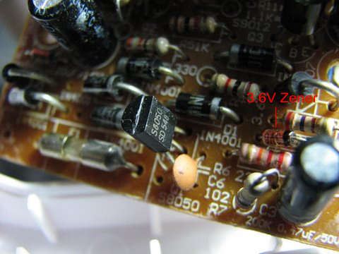
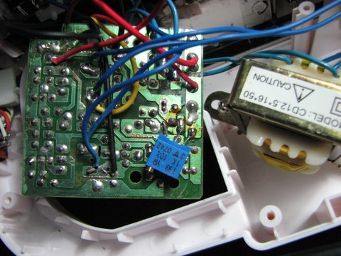
the right, you can see a part of the charging circuit. The 3.6V zener
diode feeds into the base of the S8050 transistor via a resistor-diode
pair. The transistor is configured in common-emittor mode, directly
charging the battery via the collector. Unfortunately this configuration charges the battery to 8V, which is far above the manufacturers specification. | | |
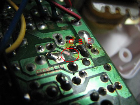
| Turning the PCB over, the CBE pins of the transistor are neatly next to each other. To lower the charge voltage, I could either use a different zener diode (which I didn't have) or use a potentiometer as a voltage divider to accurately tune the voltage. I decided on the latter. | | |
| Using a sharp craft knife, cut the track leading to the base of the transistor and carefully clean the track coming from the zener so that it can be tinned and soldered. This will be connected to the one leg of the pot (a trimpot in my case). | | |
| I bent the trimpot legs down and tinned them for easy soldering onto the PCB. | | |
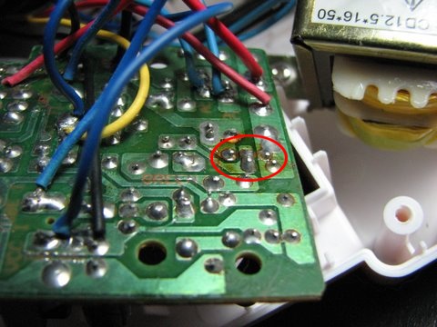
| Here you can see the trimpot soldered in place. The trimpot acts as a voltage divider between the stable voltage delivered by the zener diode and the emitter. The center-tap is connected to the base of the transistor. | | |
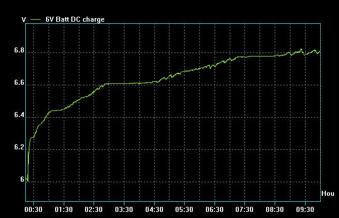
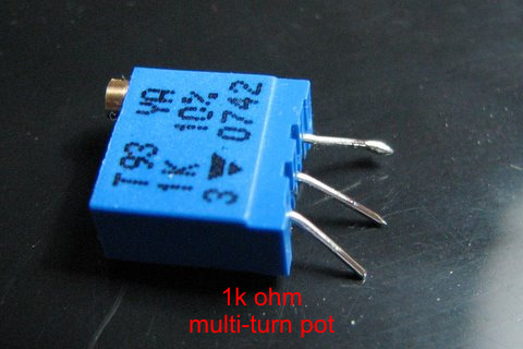
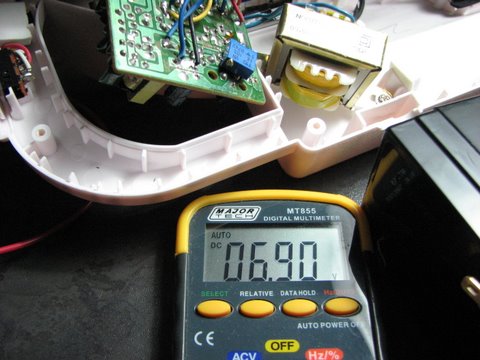
| Finally, connect a 1k ohm load to the output (i.e. where the 6V battery will go). Adjust the charge voltage to 6.9V. On a 1k ohm load, this will ensure a minimum 3mA trickle charge current to the battery, which is the internal self-discharge rate of the DELTEC BK6-4.5. | |